Thursday, December 20, 2007

A *Five* Speed Transmission

This morning, I had a spare hour, so I decided I was finally tired of only having a 3-speed transmission. Fixing it was simpler than I expected. I lifted the carpet over the center tunnel, made sure the transmission was in neutral, loosened the shifter bolt (shown below) with a 13mm socket, pushed the shifter as far right as I could, then tightened it again. Now, it's a five speed as originally intended!


At first, I tried pushing it to the left as far as it would go, but that did not help. Fortunately, right did it. I took it up to 65 MPH (above 100 KPH) just for fun, and was impressed with how smooth the ride is - a low car with a very low center of gravity makes for a pretty stable ride. And, best of all - this makes it harder to nick "Reverse" accidentally on the way to 2nd.

Also, today I passed 250 miles as an electric. 1/4 of the way to 1000...

Monday, December 17, 2007

A *Two* Car Garage

After two and a half years of being patient with my monopoly of the garage, my wife decided she wanted a space in the garage for Christmas. So, I spent yesterday afternoon organizing and cleaning, making space for our 2000 Saturn SL1. It fits pretty well, as you can see. I backed the Volt914 in so that the driver's doors face each other, so both Jill and I can easily get in.The oil spot under the Saturn is actually where the Volt914's transmission had been slowly leaking. At some point, I need to fix that...

Wednesday, December 5, 2007

Heater Installed

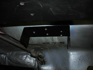
Although I was originally considering putting the heater in the rear trunk near the controller, after further reflection, I decided to put it in the passenger compartment, below the dash, between the driver and passenger. The main reason was to simplify the wiring. A secondary reason was that the heater did not fit especially well in the rear trunk. First step was attaching the heater mount to the firewall. I used rivets:


I then mounted the heater on the mount. I made sure when placing the mounting point that the heater did not interfere with any of the pedals or the steering linkage (it's hard to tell from this picture, but the steering linkage is not all that close to the heater blower):


I used 10-gauge red and black wires to deliver power from the 144-volt pack to the heater. I routed them through the original (now useless) windshield sprayer hose grommet:


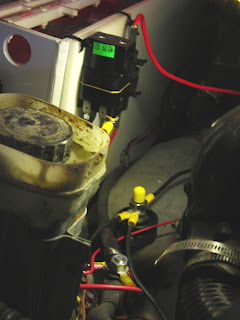
Next up was work in the middle compartment. I mounted a power post so I could attach several negative cables (the original negative cable from the most-negative point, along with negative cables to the charger and to the heater):


Next, I took the contactor I ordered...


...and mounted it on a piece of polyethylene along with the large fuse which protects the 144V heater circuit:


I hung the board from the middle battery box using tie wraps (also visible in this picture are the three wires going to the negative terminal post):


I then ran a yellow wire from the +12V input to the contactor to the switch location on the dashboard. I also ran a brown ground wire from the contactor to the grounding stud in the gas tank compartment. Note the yellow rubber cap on the negative post - I have a story to tell about that down below...


Here is the switch that will go into the dash to control the heater. The red wire goes directly to unswitched +12V (because I want the heater to be able to run without the key in the ignition). The yellow wire is split to drive the contactor and a relay for the heater blower motor in parallel:


This is the relay - a standard 12V 40A automotive relay, normally open. The yellow wire is from the switch above, the red is directly from unswitched +12V (I used 12-gauge wire since the blower pulls a fairly large current). The brown wire ties into grounding wires behind the dash. The black wire is +12V power for the blower, and the orange wire is ground for the blower:


Here's the wiring around the heater - I wrapped the contacts of the relay in electrical tape (to avoid shorts) and tucked it up above the heater:


It all works pretty well. You turn the switch on, and hot air blows out of the heater. Originally, I was going to attach hoses from that to the original heating system. However, I tried that, and the warm airflow was unsatisfactory. Fortunately, the heater is well-positioned to keep my feet toasty. I may install the flappers that came with the heater so the driver and passenger can independently control airflow.

Last, here is a wiring diagram of the heater circuits. Originally, I had the contactor and relay in series with the switch. However, this led to an excessive voltage drop which meant that the contactor did not close. So, I changed and wired them in parallel as shown here:


Remember the yellow rubber cap on the negative post I was telling you about? This is why it is here. I was tightening the bolts on the most-positive post, but my normal electric-tape-wrapped wrenches (that I use on the batteries) were not the right size for that bolt. So I used just a plain wrench. I managed to brush the top of the negative post while the wrench was touching the positive post. It resulted in a most exciting spark, including blast damage around the positive post and a flash burn on my hand that was holding the wrench:


Moral of the story: be very careful when working with high voltage... If you think you are being careful, think again, and find another way you can be even more careful. I was very lucky not to have damaged myself more than that flash burn on my left hand. I really need to get around to purchasing and installing that high current circuit breaker I've been thinking about...

Legal to Drive, Part 2, and 12V hack

As you may recall, I registered the car so it is street-legal. The State of Colorado followed up with a new title issue, which arrived today - note the FUEL option. Hopefully this will be all I need to claim the Colorado alternative energy vehicle tax credit. I've scribbled VOID over this to make it harder to use this image for nefarious purposes:


I also engaged in a little 12V hackery this week. Like TimK, I was bothered by the voltage drop caused by 20+ feet of wire between the aux battery and any devices. So, I hacked mine. I took a different approach than Tim. Figuring that the two wires were connected in the engine compartment, I just cut them at the front firewall:


And then I put ring terminals on the end of all four wires and put a 1/4-inch bolt through them. This shows two of them bolted together:


This also provides the power takeoff point for my heater. I want to be able to run it without the key inserted (on those cold winter days), so I need unswitched power. I wrapped this securely with electrical tape once I had all the wires installed on the bolt.

This helps because instead of the 20-or-so feet of wire between the aux battery and any devices (because the wire runs to the engine compartment and back before plugging into the 12V system), the "short" introduced by the ring terminals and bolt provide a much shorter current path which results in a much lower voltage drop. Previously, the 12V system was dropping to 10.3-ish volts with the lights, brake lights, and a turn signal on. Now, it stays at 11.5 or better.

Monday, December 3, 2007

Brief Maintenance Note

I got bit by a Blogger image upload bug with the last few posts. I've patched them; if you're curious what is involved, see this link.

Apologies for any inconvenience... let me know if you run into any broken image links on my blog.

Tweaking Regen Braking

I tweaked the regen braking this morning. As I mentioned earlier, the default parameters caused an oscillation or "lurching" during regen braking. I exchanged email with the support folk at Azure Dynamics about my theory - that the default 150-volt EE2NoRegenBat caused the controller to turn regen off and on as the voltage hovered near that value. The tech people agreed that setting NoRegenBat higher would be a fine workaround. I don't want to overcharge my batteries, so I decided to go with a higher NoRegenBat but a wider ramp (set by EE2RegenRamp). This chart illustrates what I did:


EE2NoRegenBat is set to 160, instead of 150, and EE2RegenRamp is set to 34, instead of 12. This had a great effect, as the following chart shows. It plots braking as a percentage of max torque (which is 53Nm with my current 100A power max for regen):


Despite the fact that the sampling period (1 second) introduces some aliasing, you can clearly see the oscillations in the old, default parameters (the blue line). The red line shows a much smoother curve, with substantially reduced lurching. I plan on leaving regen enabled from this point on to see what it does to range.

Sunday, December 2, 2007

Volt914 - A Summary

This is a summary of the process of converting a Porsche 914 from gas to electric. There is much more info in the other posts on this blog, as well as in the links to the right, so, feel free to explore. In the meantime, here's the story...

It started in September of 2005 when I purchased this 1975 Porsche 914 in Colorado Springs and drove it home to Fort Collins:


I ordered the kit from Electro Automotive, and once enough parts showed up, I started the disassembly process. The very first thing was removing the internal combustion engine. Here is the engine bay without the engine. Note the rusty area in the lower center of the picture:


Here is a closer look at the rusty spot. This is called the "Hell Hole" in Porsche 914 restoration circles. The discovery of this rust-through prompted a year-long journey into complete restoration:


I stripped the entire car down to bare metal, using a combination of citrus-based chemical strippers, an orbital sander, a wire brush on an angle grinder, and sandblasting:


I repaired the rust holes (several more than just the one shown above) and primed the car with metal-etching primer:


I painted the interior silver to match what the exterior would be. Here is the repaired hell-hole:


I then sent the car out to a professional for final paint. Here it is, back from paint and after I had installed most of the components, trim, and accessories:


The restoration complete (Fourth of July weekend 2007), it was time to complete the conversion. The kit comes in many, many pieces. Here are most of them, including the controller and motor:


The battery boxes are made out of acid-resistant plastic (polypropylene), and fit into custom-built racks and tiedowns:


The motor fits into the spot where the original motor was. It mounts to the original manual transmission. Here is a picture of the motor - it is not normally this visible, since the engine bay gets filled with 9 of the 18 batteries:


There is a fair amount of wiring to do with the kit. Here is the wiring that goes into the engine bay:


And here is the wiring that goes into the front compartment, mounted on the front battery box:


The controller sits in the rear trunk. It takes the 144 volt DC in (the two black cables going from left to right), and converts it to 3-phase AC (the really thick black cable coming from the middle). The AC drives the motor. There are a variety of other signals that go into the controller, including a motor speed sensor, throttle controls, keyswitch signals, etc.


Six of the 8-volt batteries are located in the battery box in the front compartment:


Three of the batteries are in the middle battery box, where the gas tank used to be:


And the other nine batteries are in the engine bay. This picture also shows the copper strap interconnects between the batteries. Straps are much more resistant to failure from flexing than cables:


Here is the front compartment with the boxes all closed up. The black box in the middle is the charger. You can see the charging cable plugged into the bumper at the lower right. Although you can get a 110-volt AC charger, I decided to go with 240-volt - it cuts the charging time in half (down to about 5 hours for a complete recharge). Also visible are the silver vent hoses - while charging, fans run to pull hydrogen gas out of the car so a spark does not start an explosion.


Here is a closeup of the charger plug on the front bumper:


When plugged in, the red light in the upper left of the gauge cluster is lit. And, when the charger is active, the red light on the right side of the gauge cluster lights up:


When the charge is complete, the red light on the right turns off, and the green light on the right comes on. The red light on the left is still lit, since it's still plugged in. There are interlocks that prevent the car from operating when it is plugged in, but it's still handy to have a reminder on the dash:


When you unplug the car and turn the key on, it looks pretty much just like a normal car. The green light on the lower left indicates that the 12-volt system is active. Instead of a gas gauge, there are three electric gauges - an ammeter (lower left), a high-voltage meter (top), and a 12-volt voltmeter (lower). Monitoring these gauges helps to understand the performance of the vehicle:


And that's pretty much it. The restoration took a year - from July 2006 to July 2007. The conversion itself took four months. Driving is very similar to driving a gas-operated vehicle - you still use the clutch to shift gears - but there are also differences. The biggest difference is the noise - it sounds very much like a Jetsons car! Another difference is that you do NOT push the clutch in while decelerating - because you need the wheels to turn the motor for regenerative braking. The 18 8-volt batteries (US Battery 8VGC) provide lots of energy, but they are very heavy (about 1200 pounds). The car weighs about 2900 pounds net now. In a couple of years, when it is time to replace the batteries, I hope there is some new technology available that can provide the 144 volts at substantially lower weight.

There are lots of people to thank - from TimK who was the first to assemble this kit, to the very supportive people at Azure Dynamics (the manufacturers of the motor and controller), to the staff at Pelican Parts and the community at 914world. And, most importantly - my family, who were very very supportive during this entire process.

In the next week or so, I plan on making a video with a lot of this info on it. In the meantime, if you have any questions, feel free to add them to the comment section and I'll respond.

Saturday, December 1, 2007

150 miles, and some tuning

I was out of town for 10 days since my last posting, but this past week I've been commuting exclusively with the Volt914. I hit the 150-mile mark today, and finally decided it was time to do a little tuning. The first thing to tune was the pedal - although I've adjusted the cable as much as I can, the max reading the controller sees is about 50%.

From the manual, here are the programmable parameters for the pedal:

The default settings were these:

EEXPedZero=0.1
EEXPedBrake=0.2
EEXPedAccel=0.25
EEXPedMax=0.6
This means that my pedal never hit the max acceleration. Additionally, that "0.5" reading was with the pedal completely floored - I had to screw the throttle stop almost all the way in to get that - and that was incredibly annoying (and somewhat dangerous - the pedal would sometimes stick all the way down). So, I decided to divide everything in half, so that a reading of 0.3 (30%) would hit max accel:

EEXPedZero=0.05
EEXPedBrake=0.10
EEXPedAccel=0.125
EEXPedMax=0.30
This made a huge difference - I backed the throttle stop back out to a reasonable level, and the car is definitely more responsive.

Next, I did some research on max amperage limits for my cables (2/0 welding cable) and came to the conclusion that I could raise the limit from 200 to 250 amps. These are the parameters I tweaked for that, from:

EEXNormAccelPower=19200
EEXMaxAccelPower=28800
to:

EEXNormAccelPower=24000
EEXMaxAccelPower=36000
This also made a fair difference - but it also lead to occasional controller cut-outs - where the controller stops applying power. Browsing TimK's blog, I decided to tweak down the max torque to one that matches the AC24 motor specs:

EEXAccelMaxTorque=85
EE2IsMax=375

This seems to eliminate the cut-outs. Finally, I enabled regen braking and played with it much of the day today. Unfortunately, there seems to be something weird going on. The regen cuts in, the car decelerates nicely, and then it cuts out and the car, of course, lurches. This happens at about a 1-2 second frequency. It is very annoying, and probably not good for the mechanical parts. I have a theory what's going on - see this diagram:

The main parameter is "EE2NoRegenBat", which is set to 150 volts. Above this point, the regen is not enabled. Below this point, the regen is limited until it gets below the area delimited by the "EE2RegenRamp." The theory is that the pack is below the threshold, and the regen kicks in, but that puts the net voltage abovethe threshold, and the regen cuts off. One way to test this would be to set "EE2NoRegenBat" high enough that it never cuts off, but to adjust the "EE2RegenRamp" such that not too much power is put into the battery when it is well charged.

I've posed this theory to the kind folks at Azure, and I'll wait to hear back from them before I attempt it. In the meantime, I've disabled the regen again (by setting EE2NoRegenBat way low - 100 volts - such that it never engages).

Wednesday, November 14, 2007

Legal to drive, and 100KM

I registered the volt914 yesterday. In Colorado, all that is required is:

  • A VIN verification form (get one filled out at any car dealer)
  • The original title
  • Proof of insurance
  • Driver's license
  • Normal registration fee
This presumes that you had the car legally registered when it was a gas vehicle. They retain the title, and the state will issue a new one for the new electric-only vehicle it has become.

Some day I'm going to get custom plates, but for now, I just wanted to be legal to drive. One caution - Colorado VIN verification forms have boxes for the type of vehicle - make sure to tell the car dealer that your car is all-electric *before* they fill out the form or the will habitually check the "gas" box.

Also, yesterday, I hit 63 miles on the odometer, which means the car has 100 kilometers on it as an electric. W00T! It still needs tuning (plus some other work - heaters, cosmetics, etc.), but that will have to wait a couple of weeks as my work schedule precludes me from doing much else with it for a while.

Sunday, November 11, 2007

Watering Batteries and Transmission Leak

I took the opportunity today to water the batteries. You want to do this about once a month - certainly you do not want the water level to drop down to the level of the lead plates or it can cause erosion and shorten the battery life. You make sure the batteries are fully charged, then take your jug of distilled water and fill each cell up to just below the filler cap neck. Here's one in progress in the rear compartment:


I discovered that the rearmost cells in the 5 rear batteries are nearly impossible to fill from the middle compartment, so I opened the rear trunk to access those cells:


The frontmost batteries in the rear battery box are also hard to reach, but if you push the decklid open far enough you can get the water in there:


I dropped one of my wingnuts and stuck my head under the car to retrieve it. While down there, I noticed that transmission fluid is dripping down from the motor / transmission mounting point. This is almost certainly a bad transmission mainseal. I did not replace it when I redid the clutch. It looks like I am going to regret that shortcut:


The worst thing about a leak is having to remove the motor & transmission to diagnose and fix it. The second worst thing is that, if it *is* the transmission mainseal, it has almost certainly impregnated the (brand new!) clutch disk with fluid, ruining it. I don't have time to mess with this now - I'll put a drip pan underneath to catch it until I can repair it.

In happier news, I drove to and from work on a test drive today. No problems at all - commuting will be very straightforward with the Volt914.

Saturday, November 10, 2007

A Good Day to Drive

I drove the car quite a lot today since the last post. I probably drove a total of about 15 miles, with the longest drive about 6 miles (I say "about" because I have not yet calibrated the electronic speedo. Tomorrow...). As a first step in deciding how to attack the acceleration parameters, I took a fairly long data dump - here is a chart showing some of the data from 2 minutes of that drive. First thing that jumps out is that the pedal is only pulling the throttle about halfway down. But it's not yet clear whether fixing that (or tweaking a multiplier variable in the controller) will help.

Car is road-worthy

I did a few miscellaneous things to make the car road-worthy. I adjusted the ride height, tweaked the clutch so I could shift well, and made sure the tires were well-inflated. I then took it for a 5-mile drive, at speeds up to 40MPH. Ran like a charm (acceleration is a little on the sluggish side, but nothing extraordinarily bad - I may be able to tune it up via the computer interface).

For those who were concerned about the noise the motor makes (in the previous video) I made the following video which shows what it *really* sounds like. Enjoy!

Friday, November 9, 2007

It's a car!

A quick update - Azure Dynamics was kind enough to point out some errors in my procedures, and I updated the controller with the parameters they gave me. And it's a car! Reasonably snappy acceleration and the "grinding / whining" is much lower (it sounds like a Jetson car now :-). I took my wife for a ride around the block. Well, 75% of the way around the block. I took a bump too fast and the controller turned itself off and would not turn on until things cooled down. I'll debug that tomorrow (and will adjust the ride height too).

Here's the very diplomatic message pointing out that I'm an idiot. Did I mention how fantastic Azure tech support has been?

Sunday, November 4, 2007

It's Alive!

Well, almost alive. Very, very slow. See this movie:

I spent the day yesterday disassembling the clutch & flywheel. Nothing was obviously wrong - I tweaked the tightness of the hub adapter set screws - and the hideous sound the motor makes was there even without the flywheel mounted. So, I reassembled it all, making sure all the bolts were torqued according to specs, and got back to tweaking DMOC parameters

The following are what I have tweaked so far


EEXMaxAccelPower = 43000 (was ~73000)
EE2NoRegenBat 100 (was 300)
EE2NoAccelBat 127 (was 360)
EEXNoIgnSwitch = 1 (was 0)

I set EE2NoRegenBat down so low because the regen was coming on all the time (as evidenced by the brake lights coming on). EEXMaxAccelPower had no perceptible affect. And nothing happened until I set EEXNoIgnSwitch to 1 (tells the DMOC it does not need an external "ignition switch" signal) and EE2NoAccelBat to 127 (it thought my batteries were way too low to run).

I suspect there is much tuning ahead of me. As usual, Azure Dynamics has been very helpful. I sent off a complete dump of parameters along with 30 seconds of data capture; we'll see what recommendations they have for tuning.

Wednesday, October 24, 2007

DMOC returns...

No pictures, sorry. My DMOC445 returned from its two-week journey to Azure, filled with new firmware. I dropped it in, wired it up, and turned it on. This time, the ccShell 3.0 program talked to it just fine. I set the "EEXNoIgnSwitch" variable to 1, and pressed the throttle. Success! Noise from the controller and noise from the motor. Hmm. And noise from the clutch. A grinding kind of noise. And the wheels don't turn. Something in there needs an adjustment, and I may have to drop the engine/tranny to do it... Stay tuned.

Monday, October 22, 2007

Charger Dash Lights

I'm working my way through my list while the controller is getting its firmware updated (scroll to the bottom of this post for the list). Tonight, I attached the rear valence and hung the rocker panels (with the screws - I need to get new rivets to finish the job). I also wired up lights from my charger to my dashboard. Remember the Zivan NG3 built-in relay:


Those "Aux2" relays are perfect for driving two panel lights, one that lights when the charger is active, and another that lights when the charge is complete. First, I attached wires to the charger "aux2" outputs:


These wires go to a screw-in terminal block that I installed next to the charger mount, on the driver's side. Also going to this terminal block are the input +12V (to the second-from-bottom left terminal) and the fan +12V control (from the bottom right terminal) - this lets the fans be driven when the charger is going (although TimK points out that hydrogen is still outgassing for several minutes after the charger turns itself off; I'm considering moving the fans to always be on when the system is plugged in):


I then took these wires into the passenger compartment, and used them to drive some lights. The top-left red light now comes on whenever the car is plugged into AC. The red light on the right comes on when the NG3 is charging:


...and when the charge is complete, the green light on the right comes on (the red light on the top left is still on, because the car is still plugged in - exactly as I want it):


I have not yet screwed the gauge surround into the dash, since I still need to wire the heater control.